Cooper Clad Steel Coils(For Asia customer)
Application
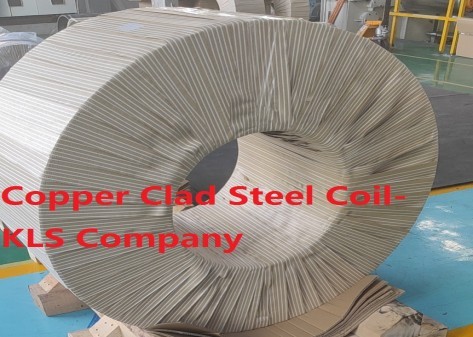
We take great pride in being able to supply our triply clad steel coils/cooper clad steel coils to our Asia customer for their newly-developed design equipment. The material combination is copper clad stainless steel 316 clad copper. That is to say, the sandwich type. And the thickness combination is (0.5 + 0.4 + 0.5) mm. The ball core is Φ500, and the sizes can be customized for all of our customers. We will put these clad steel coils into the wooden package so as to avoid any possible damage during the transit and storage. With us, all of our wooden cases come with fumigation certificate. your order is safe, and your project is safe.
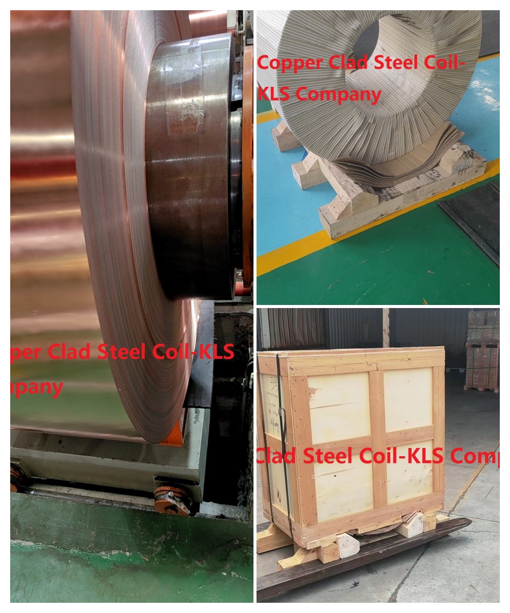
The material was supplied in coil form so that the customer could integrate it into its own component manufacturing process. Instead of using a single metal, the project combined two copper working surfaces with a stainless steel center layer in one continuous material.
| Project Item | Confirmed Specification |
|---|---|
| Customer Region | Asia |
| Project Use | Material for a component in newly developed equipment |
| Delivery Form | Three-layer clad coil |
| Layer Sequence | Copper / Stainless Steel 316 / Copper |
| First Copper Layer | 0.50 mm |
| SS316 Core Layer | 0.40 mm |
| Second Copper Layer | 0.50 mm |
| Total Thickness | 1.40 mm |
| Structural Type | Symmetrical sandwich structure |
| Coil Core | Φ500 |
| Other Coil Dimensions | Customized according to the approved order requirements |
| Export Packaging | Wooden case with fumigation certificate |
The coil was intended as feedstock for a component in the customer’s newly developed equipment. Its layer structure was defined at the individual-layer level because surface function, structural support, forming behavior and total thickness all affect the finished component.
The two 0.50 mm copper layers provide a copper working surface on both sides of the material. Depending on the final component design, these surfaces can support heat transfer, electrical contact or copper-side joining requirements.
The 0.40 mm SS316 center layer provides stainless steel support within the 1.40 mm total thickness. It helps the material retain the structural characteristics required by the equipment component while avoiding the need to manufacture and assemble three separate metal sheets.
Actual conductivity, heat-transfer performance, rigidity and joining behavior depend on the selected copper grade, material temper, part geometry and downstream process. These requirements must therefore be defined in the customer’s technical specification and verified with order-specific results rather than generic material data.
The following table shows the layer arrangement from one outer surface to the other. The representation is not to scale.
| Cross-Section Position | Material | Layer Thickness | Role in the Structure |
|---|---|---|---|
| Outer Working Surface | Copper | 0.50 mm | Provides a copper surface on the first side |
| Center Core | Stainless Steel 316 | 0.40 mm | Provides the stainless steel supporting layer |
| Opposite Working Surface | Copper | 0.50 mm | Provides a copper surface on the second side |
| Total | Cu/SS316/Cu | 1.40 mm | Integrated three-layer coil |
The equal copper thicknesses on both sides create a balanced layer arrangement. This structure is suitable for projects that require copper surfaces on two faces while retaining stainless steel in the center of the component.
A clad coil should be approved according to the customer’s actual production route. Slitting, stamping, bending, forming and joining can place different demands on the layer interfaces, edges and surface condition.
Before slitting, the final strip width, width tolerance, camber, edge condition, burr direction, coil core, maximum outer diameter and coil weight should be confirmed. Slitting parameters must protect both copper surfaces and prevent unacceptable edge deformation.
For stamped or formed components, the customer should provide the part drawing, forming depth, tool clearance, material orientation, lubricant requirements and required surface direction. Material temper and layer bonding must be matched to the actual forming load.
A representative forming trial is recommended before mass production when the finished component includes deep draws, sharp transitions or multiple forming stages.
The bend direction, bend radius and material orientation should be defined in advance. Trial parts can be inspected for surface cracking, excessive edge deformation or separation at the copper–stainless steel interfaces.
The intended joining method must be identified during material confirmation. Soldering, brazing, resistance welding and mechanical fastening involve different surface, filler, flux and heat-input requirements. The joint should therefore be validated using the actual copper face, part geometry and production conditions.
Because this is a custom multilayer coil, acceptance is based on the approved project specification rather than catalogue averages. Layer thickness, coil dimensions, surface condition and bond quality should be checked using the sampling method and tolerances agreed for the order.
| Inspection Item | Inspection Focus | Acceptance Basis |
|---|---|---|
| Material and Layer Sequence | Confirmation of copper / SS316 / copper arrangement | Approved technical specification |
| Individual Layer Thickness | 0.50 / 0.40 / 0.50 mm at agreed sampling positions | Order-specific layer tolerances |
| Total Thickness | Confirmation of 1.40 mm total gauge | Approved total-thickness tolerance |
| Coil Dimensions | Width, Φ500 core, outer diameter and coil weight | Purchase order and approved drawing |
| Edge Quality | Burr, edge deformation and slit condition where applicable | Agreed downstream processing requirements |
| Surface Quality | Scratches, dents, oxidation, contamination and other visible defects | Approved surface criteria or reference sample |
| Bond Integrity | Condition of the two copper–SS316 interfaces | Agreed test method and sampling plan |
| Functional Performance | Electrical, thermal or mechanical properties when required | Batch-specific inspection or test report |
Numerical values for conductivity, thermal conductivity, tensile strength, elongation or bond strength should only be stated when they were included in the project inspection plan and recorded for the supplied batch. Generic copper or SS316 values are not presented as results for this order.
After inspection, the coil was placed in a wooden case to reduce the risk of damage during transportation and storage. The wooden export case was supplied with a fumigation certificate for international shipment.
Coil identification, material structure, order number and packaging requirements should be confirmed before dispatch so that the customer can match the received coil to the correct equipment project and processing specification.
For a similar custom coil project, please provide:
◆ Copper and stainless steel grades
◆ Required layer sequence
◆ Thickness of each layer
◆ Total material thickness
◆ Coil width, core diameter and maximum outer diameter
◆ Maximum coil weight
◆ Part drawing or component dimensions
◆ Slitting, stamping, bending, forming or joining method
◆ Required dimensional tolerances
◆ Surface and edge requirements
◆ Required inspection methods and documents
◆ Export packaging requirements
View our copper clad steel coil capabilities or contact KLS with your layer structure, drawing and downstream processing requirements. We will review the material combination, manufacturable dimensions and inspection scope before quotation.
This thickness combination was supplied for this specific equipment project. Other copper and stainless steel thickness ratios can be reviewed according to the required total thickness, component function and downstream processing method.
Please provide the required width, coil core diameter, maximum outer diameter, maximum coil weight and any dimensional tolerances required by your feeding, slitting or forming equipment.
Required inspection items and documents should be agreed before production. Any reported conductivity, mechanical property or bond-quality value must correspond to the applicable batch and order-specific test record.